Modern DC-DC chargers with solar input—like units from Renogy, Victron, Enerdrive, and Redarc—make it easier to charge lithium or AGM batteries from both your vehicle alternator and solar panels simultaneously.
But many owners run into issues when wiring solar, especially with dual-input models.
This guide explains how priority logic, MPPT voltage/current limits, and panel sizing per input work—so you can wire safely and get maximum charge efficiency.
⚡ 1. What “Dual-Input” Means
A dual-input DC-DC charger accepts two charge sources:
| Input | Typical Source | Function |
|---|---|---|
| Input 1 | Vehicle alternator (DC) | Primary charge while driving |
| Input 2 (PV) | Solar panels | Independent MPPT solar input |
The charger automatically prioritises solar when sunlight is available, reducing alternator load and saving fuel. When solar drops off (clouds or night), it seamlessly switches to alternator input.
? Tip: In most units, solar always takes priority when voltage is detected at the PV terminals.
? 2. Typical Priority Logic (Redarc / Victron / Renogy Example)
| Condition | Priority |
|---|---|
| Solar voltage above MPPT start (≈ 18 V) | ✅ Solar (PV) takes priority |
| Solar below threshold | ? Alternator automatically engages |
| Both inputs active | ⚙️ Solar charges until shaded or battery nears full, then alternator tops up |
| Engine off + no solar | ⚠️ Charger goes into standby |
Practical Flow:
☀️ Daytime: PV input runs charger → alternator idle
?️ Cloudy / night: PV voltage falls → alternator resumes
? Driving + solar available: MPPT takes main load, alternator assists if needed
⚙️ 3. MPPT Voltage & Current Limits
Every DC-DC charger’s solar input has maximum electrical limits—exceeding them can trigger “PV Over-Voltage” or permanently damage the controller.
| Example Model | Max PV Voltage (Voc) | Max PV Current | Max Input Power |
|---|---|---|---|
| Redarc BCDC1225D | 32 V | 520 W @ 12 V | 25 A |
| Renogy DCC50S | 25 V | 25 A | 400 W |
| Victron Orion-Tr Smart + SmartSolar | 100 V (SmartSolar MPPT) | 20–35 A | Model-dependent |
| Enerdrive ePOWER 40 A | 45 V | 600 W | 40 A |
⚠️ Important: Always keep your open-circuit voltage (Voc) at least 10 % below the rated maximum, especially in cold weather where Voc rises.
? 4. Panel Sizing per Input
Step 1 – Check Charger PV Voltage Range
Find the PV input voltage window in your manual (e.g. 18–32 V).
Step 2 – Choose Series or Parallel Wiring
12 V charger (PV max 30 V): use 1 × 12 V panel or 2 × 12 V panels in parallel
24 V charger (PV max 45 V): use 2 × 12 V panels in series
48 V input MPPT: use 3–4 × 12 V panels in series
Step 3 – Confirm Panel Voc
Example for a 400 W 12 V panel:
Voc = 22 V → two in series = 44 V → ✅ Safe for 45 V limit
But three in series = 66 V → ❌ Exceeds limit
Step 4 – Confirm Array Current
Two 400 W panels in parallel (~13 A each) = 26 A total → fits within a 25 A PV limit only if using high-quality wiring and short runs.
? 5. Common Wiring Layouts
A. Single Solar Input (Most Common)
Panels → MPPT input → Battery via charger
Ideal for smaller caravans or camper trailers.
B. Dual Solar Arrays (Advanced Split Setup)
If your DC-DC supports dual PV inputs (e.g. Bluetti Apex-300, Victron SmartSolar Dual), wire separate strings per input:
| PV Input 1 | PV Input 2 | System Example |
|---|---|---|
| 3 × 400 W panels in series | 3 × 400 W panels in series | 2 400 W total into dual MPPT inputs |
Each input operates independently, preventing mismatch losses and keeping both trackers in their optimal voltage zone.
? 6. Voltage Drop & Cable Gauge (Critical for 12 V)
For 12 V systems, small losses equal big efficiency hits.
| Array Power | Cable Length | Recommended Cable |
|---|---|---|
| ≤ 400 W | ≤ 3 m | 6 mm² (AWG 10) |
| 400–800 W | 3–6 m | 8 AWG (10 mm²) |
| 1 000 W+ | 6 m+ | 6 AWG (16 mm²) |
Keep PV-to-charger runs as short as possible and use crimped MC4s to maintain waterproof connections.
? 7. Troubleshooting Common Issues
| Symptom | Likely Cause | Fix |
|---|---|---|
| “PV Over-Voltage” fault | Series voltage too high | Re-wire to fewer panels in series |
| No solar charge | Polarity reversed / shading / MC4 loose | Check with multimeter |
| Alternator not engaging | Ignition trigger wire inactive | Confirm wiring & voltage sense |
| Charger oscillates | Low battery or undersized cables | Upgrade wiring & fuse size |
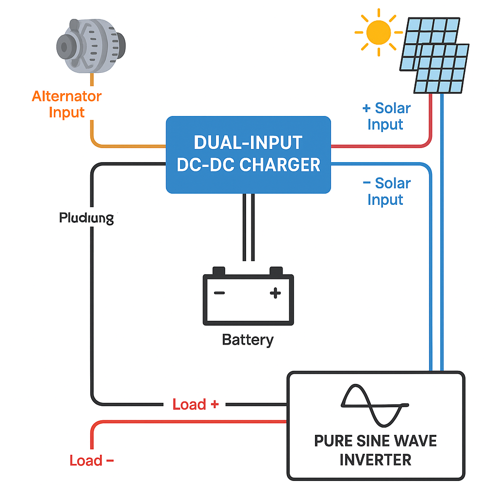
?️ 8. Visual Diagram – Dual-Input Logic & Panel Connection
Below is a clear overview showing alternator + solar inputs, priority switching, and series/parallel examples for panel sizing.
Diagram 1 – Dual-Input DC-DC Priority Flow
? Solar → Primary → Battery
? Alternator → Secondary (backup)
Both feed into the same DC-DC charger → battery → load → inverter.
✅ 9. Quick Reference Table
| Charger Type | PV Limit (V) | Recommended Panel Config | Ideal Use Case |
|---|---|---|---|
| 25 A 12 V (≤ 32 V PV) | 1 × 12 V panel (18–22 V Voc) | 200–400 W campers | |
| 40 A 24 V (≤ 45 V PV) | 2 × 12 V panels in series (40–44 V) | 400–800 W caravans | |
| 60 A 48 V (≤ 100 V PV) | 3–4 × 12 V panels series (66–88 V) | 1–2 kW off-grid cabins |
? 10. Key Takeaways
Solar always takes priority over alternator input.
Never exceed the MPPT’s maximum Voc rating.
Use series wiring for higher voltage; parallel for higher current.
Size cables for < 3 % voltage drop.
Balance both inputs for efficient, automatic charging.
Was this article helpful?
That’s Great!
Thank you for your feedback
Sorry! We couldn't be helpful
Thank you for your feedback
Feedback sent
We appreciate your effort and will try to fix the article